To be used in future
Prev Section 5.7: Semi-classical limit
Up Chapter 5: Path Integrals
Section 5.9: Brownian Motion Next
5.8 Slits
5.8.1 Single slit
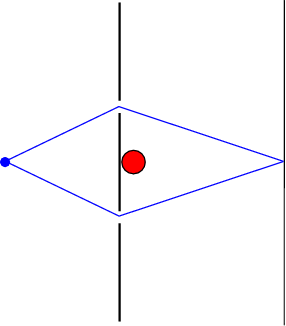
The path integral is particularly useful to describe impenetrable walls; they can just be interpreted as a limit on the paths that are allowed to contribute to the path integral. For instance, it is not that easy to understand the diffraction by a slit, see Fig. 5.2↓.
If we have a source at the point
emitting a stream of particles given by the wave function (or complex amplitude)
, the amplitude at a point
on the screen at time
is given by the propagator
This can easily be written as a sum over all allowed paths using the path integral, and explains why we see interference. We can split the propagation in one to the slit and from the slit to screen:
The two propagators can to a good extent be approximated by a free propagator (not exact, since not all paths are allowed).
5.8.2 Aharonov-Bohm II
Now consider a double slit experiment with electrons where we place an impenetrable cylinder containing a magnetic field directly behind the slits, so that the electrons either go around one way or another. Suppose the cylinder is placed against the area between the slits, so that electrons have to go either above the cylinder, if they go through the slit at the top, or below the cylinder, if they go through the lower slit. If we look at the phase difference between any two paths above and below, we find from
that
The additional phase difference is thus independent of the paths, as long as they pair up below and above. Thus we find that the interference pattern shifts to accommodate this new phase shift, even though the electrons have nowhere been exposed to the magnetic field!


